
Seeing Beyond
Since the beginning of astronomical observations in antiquity, humans sought a way to enhance the light-gathering capabilities of our eyes. Initially, the focus was on the visible spectrum: it appears that in the early 1600s, the first telescopes were already circulating in the Netherlands, although not for scientific-astronomical use. It was only in 1609 that Galileo Galilei constructed and perfected the first simple model of a refracting telescope. He was probably the first to methodically study its operation and certainly the first to understand its potential. Even though it had only a plano-convex (converging) lens used as an objective and a plano-concave (diverging) lens as an eyepiece, and it provided only a ninefold magnification, it allowed him to observe Jupiter's satellites and lunar craters. From that moment onwards, astronomy experienced a new beginning.
Unfortunately, the major problem with the Galilean (and later Keplerian) model of telescopes was the lenses themselves, which were afflicted with chromatic and spherical aberrations, partly due to their still approximate construction. Another innovation was needed, and it was Isaac Newton who, in 1668, designed a new type of telescope based on mirrors instead of lenses. The beam from the curved (parabolic) mirror was made to converge onto a secondary mirror and then sent to an eyepiece: this gave birth to the reflecting telescope.
The technical evolution of astronomical instruments progressed rapidly, both in the optical field and, starting from the 1930s, in radio astronomy. It was a chance discovery that allowed Karl Guthe Jansky to find a constant radiation with a peak of intensity toward the center of our galaxy. The first radio telescope was built by Grote Reber in 1937, a 9.4-meter paraboloid that allowed its creator to confirm Jansky's initial measurements, subsequently creating a complete map of our galaxy. It was only from the 1950s onward that radio astronomy gained ground and began its significant development.
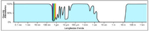
Seeing beyond, however, primarily means overcoming a significant obstacle: our atmosphere. This is opaque only at certain wavelengths. As shown in Figure 2, the atmosphere is transparent only in specific regions known as "windows": the optical window (between 300 nm and 800 nm), which coincides with the human eye's sensitivity range, the infrared window (from 700 nm to 1.3 μm), and the largest window, the radio window, which also includes microwaves (from 1 mm to about 20 m). For this reason, ground-based observation is limited to the use of optical telescopes and radio telescopes. The remaining bands, particularly infrared, ultraviolet, and highly energetic bands like X-rays and gamma rays, can be observed almost exclusively through orbital telescopes or those placed on high-altitude balloons.
Optical Telescopes
The name "telescope" is derived from the Greek words τηλε (tēle), meaning "far," and σκοπεῖν (skopein), meaning "to look" or "to see." It is a word coined by the Greek mathematician Giovanni Demisiani (Ἰωάννης Δημησιάνος) in 1611, during a meeting for the election of Galileo Galilei to the Lincean Academy.
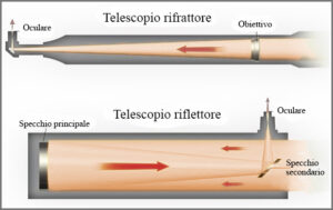
The optical configurations of telescopes can be divided into two categories (Fig. 3). Refracting telescopes, which use a set of lenses to exploit the refraction of light to focus the image. Reflecting telescopes, which collect light by utilizing the phenomenon of light reflection through the use of a concave mirror, often parabolic (but not exclusively), concentrating it at the focus, from which it can be observed and analyzed.
Refractor Telescopes
Refraction is an optical phenomenon that causes the bending of a wave when it passes from one medium to another with different refractive indices, where the propagation speed changes, following Snell's law:
n1 sinθ1 = n2 sinθ2
Where n1 and n2 are the refractive indices of the two materials being traversed, θ1 and θ2 are respectively the angles of incidence and refraction.
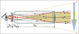
As already mentioned, refracting telescopes consist of an objective and an eyepiece. The objective is a lens system that collects light from an object and focuses the rays to produce a real image. It can also be made up of just a converging lens placed between the first focus and infinity. The eyepiece is a lens system enclosed in a barrel, which allows the formation of a virtual image of the object, thus accessible to the human eye. The magnification that can be achieved depends on the ratio between the focal length of the objective and the focal length of the eyepiece. If you divide the telescope's focal length by the eyepiece's focal length, you get the magnification (I):
I = f_ob/f_oc
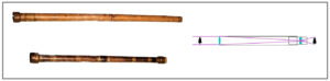
In this way, the optical system reverses the observed image. The upright image is provided by a Galilean-type configuration (see Fig. 1). However, the advantage of the Keplerian-type eyepiece is that the image is concentrated at the focus, and the eye placed at the exit pupil collects all the light and sees the entire field, whereas with the Galilean eyepiece, it is necessary to move the eye to see the entire image completely.
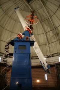
The significant next step in the evolution of refracting telescopes was the invention of the achromatic lens, a lens with multiple elements that solved the problem of chromatic aberration and allowed for shorter focal lengths. A subsequent evolution (1886) was the apochromatic refractors (combining at least 3 different glasses), constructed with special materials with very low dispersion (typically Flint glass, Crown glass, and often fluorite glass), capable of focusing light of three different wavelengths (blue, green, and red) at the same point. Unfortunately, despite these improvements, the size of the lenses in refracting telescopes must be limited, as the lens deforms under its own weight since it can only be supported at its edges, unlike a mirror that can be supported on the back. For this reason, the world's largest refractor has a diameter of "only" 102 cm and is located at the Yerkes Observatory (University of Chicago, 1897).
Reflecting Telescopes
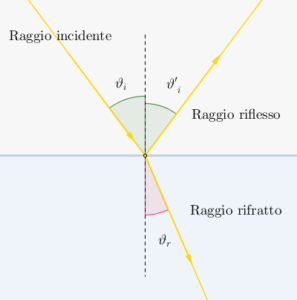
Reflection is the phenomenon in which a wave, propagating along the interface between different media, changes direction due to an impact with a reflective material. The reflection of light follows the experimental law, known as Snell's-Cartesian law, which states that the incident ray, the normal to the reflecting surface at the point of incidence, and the reflected ray lie in the same plane. Furthermore, the angle of incidence θ1 is equal to the angle of reflection (Fig. 4).
The first reflecting telescope was designed and invented by James Gregory in 1661 and later became known as the Gregorian telescope. It was then built, with some modifications, by Newton in 1668, although the priority in the invention of the reflecting telescope is still a subject of discussion, attributed to either astronomer Hooke or Newton.
Reflecting telescopes use a concave mirror (primary) for the objective and one or more smaller, appropriately shaped mirrors (secondary). By using reflective surfaces, light rays do not undergo refraction, and the produced images are therefore free from chromatic aberration. Furthermore, by choosing the shape of the surfaces wisely, it is possible to eliminate geometric aberrations to provide optically correct images. Reflecting telescopes can be distinguished into several categories based on the different mirror configurations:
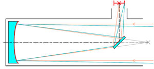
Newtonians
The classic configuration, invented by Isaac Newton back in 1668, involves a parabolic primary mirror that focuses the light onto a focal point. Before reaching this point, the light rays are intercepted by a flat mirror with an elliptical shape inclined at 45° (secondary mirror), which reflects them toward a side hole in the tube, where the eyepiece is placed. This type of telescope has limited ability to correct off-axis geometric aberrations and is generally quite long, with a length comparable to the equivalent focal length defined by the primary mirror.
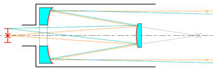
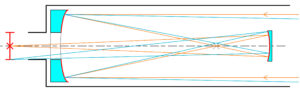
Cassegrain
The Cassegrain telescope is constructed with a concave parabolic primary mirror and a convex hyperboloid as the secondary mirror. The secondary mirror intercepts the converging beams at the primary focus before they reach it. The primary focus coincides with one of the two geometric foci of the hyperboloid, while the other is located behind the primary mirror, which is perforated, and serves as the focus of the telescope. This telescope has the advantage of being much shorter than its equivalent focal length. Due to the challenging manufacturing process of the secondary mirror, Cassegrain telescopes had a slower evolution, but today, they are widely used among astronomers and stargazers for their combined power (focal length) and portability.
An important variation of the classic Cassegrain telescope is the Ritchey-Chrétien telescope, which still uses two mirrors, one primary and one secondary, but this time both are hyperboloids. This significantly reduces the effects of off-axis aberration. It has only one aberration, astigmatism, but no spherical aberration or coma, thus increasing the corrected field. Even astigmatism can be eliminated by introducing a third curved optical element. When this element is a mirror, the result is a three-mirror anastigmatic telescope.
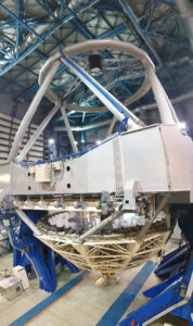
Fig.9: The Very Large Telescope VLT (Chile)
The world's largest telescopes have been adopting this configuration for quite some time. Among the most important ones, we can mention the European Southern Observatory's Very Large Telescope (VLT) in Chile with its four 8.2-meter diameter telescopes and the Gran Telescopio Canarias at the Roque de los Muchachos Observatory in Spain with a 10.4-meter diameter.
There is also another variant of the Cassegrain telescope: the Nasmyth configuration. In this case, a third mirror (flat) is added to the classic Cassegrain configuration, located along the instrumental declination axis, which brings the focus outside the axis. Observation of the source then occurs at the end of the declination axis where the observation instruments are placed. In a Nasmyth telescope, there is no need to perforate the primary mirror.
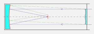
Gregorians
The Gregorian telescope, described by the Scottish astronomer and mathematician James Gregory in his 1663 book "Optica Promota," uses two concave mirrors. The primary mirror, a concave paraboloid, collects light and converges it towards a focus located in front of the secondary mirror, a concave ellipsoid, which reflects the image backward through a hole in the primary mirror. This produces a non-inverted image, which is also useful for terrestrial observations. Some small telescopes are still built in this manner. Several large modern telescopes also use a Gregorian configuration, such as the Large Binocular Telescope in Arizona or the Magellan telescopes at the Las Campanas Observatory in Chile.
Catadioptric
The catadioptric telescope is a type of telescope that relies on an optical system consisting of mirrors and lenses. In such a telescope, which can be described as a hybrid between a refracting telescope, which uses lenses, and a reflecting telescope, based on mirrors, both the principles of refraction and reflection of light are utilized. An example of a catadioptric telescope is the Schmidt telescope (1930), which consists of a concave spherical primary mirror, a curved focal plane, and a corrective lens that reduces spherical aberration, placed at the center of curvature of the primary mirror. It is a photographic camera designed to provide wide-field photographs. It is called a Schmidt camera precisely because it is primarily aimed at astrophotography.
Differences between lenses and mirrors
We have seen how mirrors have some advantages over the use of lenses. The latter are made of high-quality glass, such as Crown, with a high refractive index and low dispersion, usually combined with other lenses made of Flint glass, which also has a particularly high refractive index (1.6-1.89) and a dispersion around 0.017. These characteristics make it suitable for optical glasses such as prisms and achromatic lenses, although there are still problems with chromatic aberration and structural stability in large lenses.
For mirrors, on the other hand, there is no chromatic aberration, no light absorption like in glass (there is a minimal percentage of loss caused by the reflective material), and since they have a single surface, they are easier to construct and clean, and it is easier to keep them in position. However, they obviously require a curvature like lenses, and they are more susceptible to degradation of the reflective surface over the years. The quality of mirror optical processing is crucial for the telescope's performance: ideally, all photons reflected by the mirror should converge at a single point, the focus, but imperfections in processing cause image blurring. Processing must be done in such a way that the largest imperfections on the mirror are a small fraction of the wavelength of the received light (1/100λ), typically in the nanometer range.
Glass, used for mirror manufacturing in the first half of the 20th century, is very sensitive to temperature variations. For this reason, mirrors have been made with other materials ranging from borosilicate (common pyrex) to ULE (Ultra Low Expansion), fused quartz, CerVit (vitrified ceramic), and Zerodur (with which the 4 mirrors of 8.2 meters in diameter each of the ESO's Very Large Telescope, VLT, were built), which have virtually zero coefficients of thermal expansion. In many cases, mirrors are constructed with a honeycomb structure that guarantees both lightness and rigidity.
The correct reflective material coating is also of fundamental importance: the reflective metals usually used for astronomical mirrors are Aluminum (Al), Silver (Ag), and Gold (Au). The performance of aluminum and its relative cost have made this material the most widespread (aluminization process), although recent studies have highlighted a new technique for creating protective coatings on silver-based reflective films (silver coating) for large astronomical mirrors. This technique is called atomic layer deposition and involves creating an extremely thin layer of material by depositing one molecular layer at a time, ensuring high thickness uniformity on the surface. The purpose is to increase the available observing time, limiting maintenance operations, which with silver must be more frequent due to its ease of oxidation in aggressive atmospheric conditions. Gold's reflection characteristics are suitable only for infrared observations, as its reflective power decreases drastically towards the blue part of the spectrum but increases well beyond the capabilities of aluminum and silver beyond 700nm.
Mounts
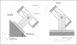
Telescopes require stable supports that allow for smooth and precise pointing of the object under examination as well as tracking it across the celestial sphere. For terrestrial telescopes, there are two main types of mounts: equatorial and altazimuth.
In the equatorial mount, one of the axes is directed toward the Celestial North Pole (or South Pole). This axis is called the polar axis or hour angle (right ascension coordinate). The other axis, the declination axis, is perpendicular to it. Because the hour angle axis is parallel to the Earth's rotation axis, the apparent rotation of the sky can be compensated by rotating the optical axis around the hour angle axis at a constant rate.
In the altazimuth mount, one axis is vertical, and the other is horizontal. It is an easier mount to construct than the equatorial mount and is more stable for large telescopes that need to support significant weights. In this case, however, to track the rotation of the sky, the telescope must be rotated in both axes and at variable speeds. Furthermore, if an object is near the zenith, its azimuth will change rapidly, making its observation more challenging.
The largest telescopes were traditionally built on equatorial mounts until, with the development of computers, it became possible to implement complex altazimuth tracking with them. Many of the more recent telescopes are, in fact, placed on altazimuth mounts. However, it is clear that with this mount, the observed field rotates around the celestial pole over time, and therefore, acquisition instrumentation (CCD camera, spectrograph, etc.) is rotated to compensate for this effect using a system called a field derotator.
Adaptive Optics
Despite the "windows" of visibility in the electromagnetic spectrum, the images produced by ground-based optical telescopes are also affected by distortions due to the fact that light, passing through various layers of the atmosphere, is strongly subject to seeing phenomena. These phenomena cause the source to appear not as a point source but as an extended disk with variable brightness (Airy disk). In theory, an ideal instrument is capable of collecting approximately 84% of the incident radiation contained in this disk. The radius of the Airy disk allows us to calculate the maximum angular resolution of the instrument θmax:
θmax = 1.22 λ/D
Where D is the diameter of the instrument, and λ is the wavelength of the incident light. Atmospheric turbulence thus deviates the light radiation, and some beams arrive on the sensor before others, causing a "twinkling" effect of the source. Due to this continuous movement of air masses, the precision of a ground-based telescope rarely falls below 1 arcsecond, compared to the 0.05 arcseconds of the Hubble Space Telescope.

This phenomenon can be mitigated by placing the telescope at high altitudes and in dry, desert-like areas on the planet.
The ultimate solution, however, is the use of adaptive optics. The principle of operation is based on the use of a laser beam to create an artificial guide star (laser guide star, LGS). Typically, laser light at 589nm is used to resonantly excite sodium atoms higher up in the mesosphere and thermosphere at an altitude of around 70km, making them appear to "shine." The LGS can then be used as a reference for the wavefront, just like a natural guide star, which may not always be present in the field of observation. The distorted image of the LGS caused by the atmosphere is analyzed by a wavefront sensor in a timescale of milliseconds, and the computer calculates the optimal shape of the mirror to correct the distortions, reshaping the surface of the deformable mirror using thousands of mechanical actuators.
In the next article... radio telescopes!